
Aplicaciones de ozono
How Oxygen Concentrators Work
How an Oxygen Concentrator “Makes” Oxygen
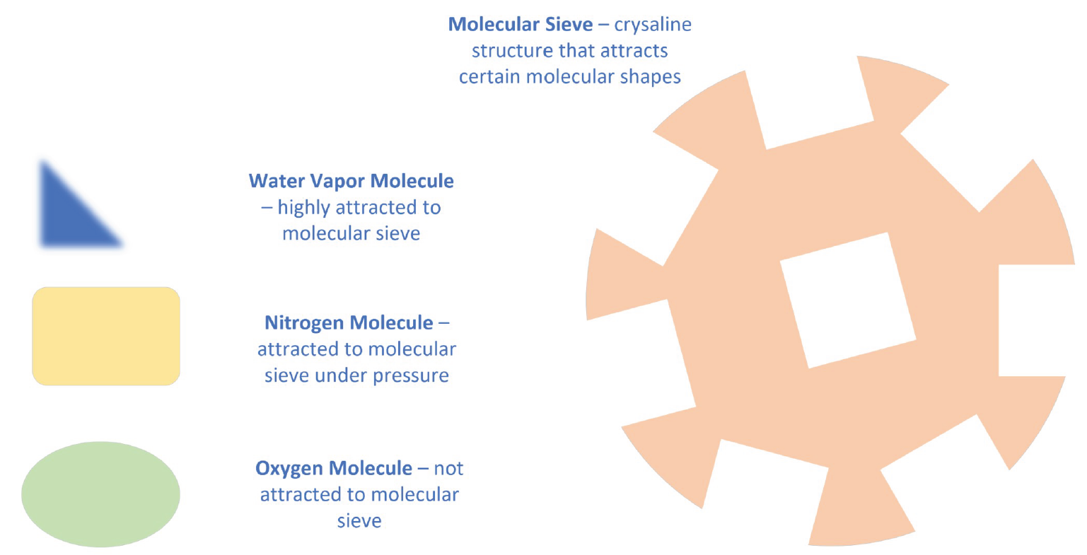
An oxygen concentrator provides 95% oxygen by removing the nitrogen and water vapor from air. It removes the nitrogen and water vapor by passing the air through molecular sieve. This molecular sieve, also called zeolite, is modeled below with the shape that looks and acts something like a sponge. The molecular structure of the surface is “sticky” to water vapor and nitrogen molecules. Like a sponge, the surface area is multiplied by the cavities that permeate the material.
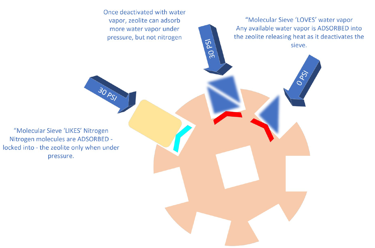
Water vapor is highly attracted to molecular sieve and is the first to be adsorbed into the crystalline structure. Water vapor forms a tight bond that de-activates the molecular sieve and releases heat energy. This water can only be removed with a special heat treatment.
Nitrogen is adsorbed into the molecular sieve only under pressure. It will only bind to molecular sieve that has no water vapor already adsorbed.
Once adsorbed, the gas molecules become part of the solid structure of the zeolite and therefore take up much less volume than they did as a gas.
Activated molecular sieve material is placed in a sealed cylinder called the “sieve bed.” Air is pushed into a port at one end of the sieve bed with an air compressor.
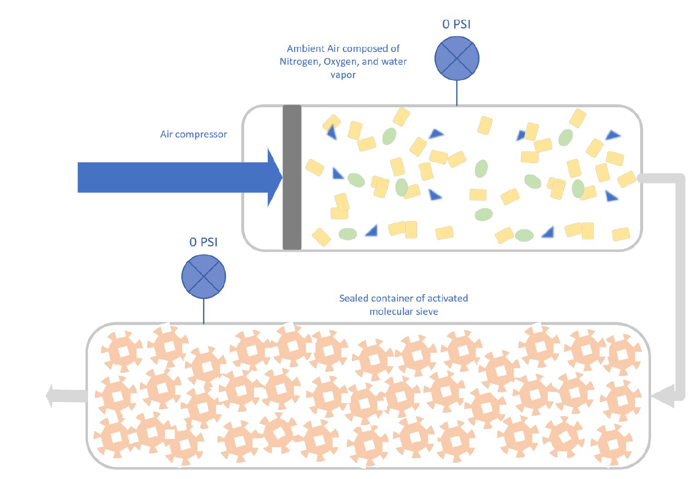
As air is pushed into the sieve bed, the molecular sieve begins to adsorb first the water vapor.
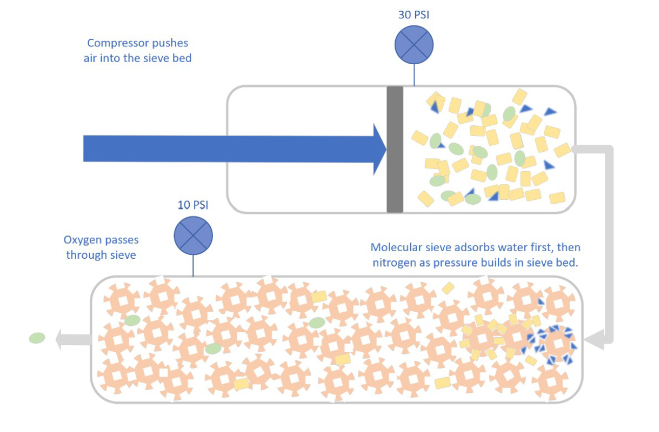
As pressure builds, nitrogen will be adsorbed into the molecular sieve and oxygen continues to the opposite end through an exit port into a storage tank.
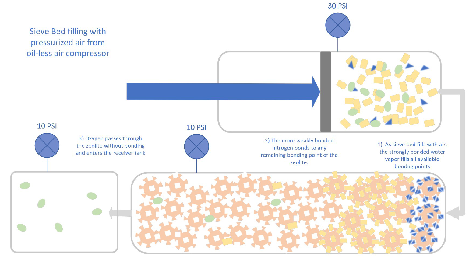
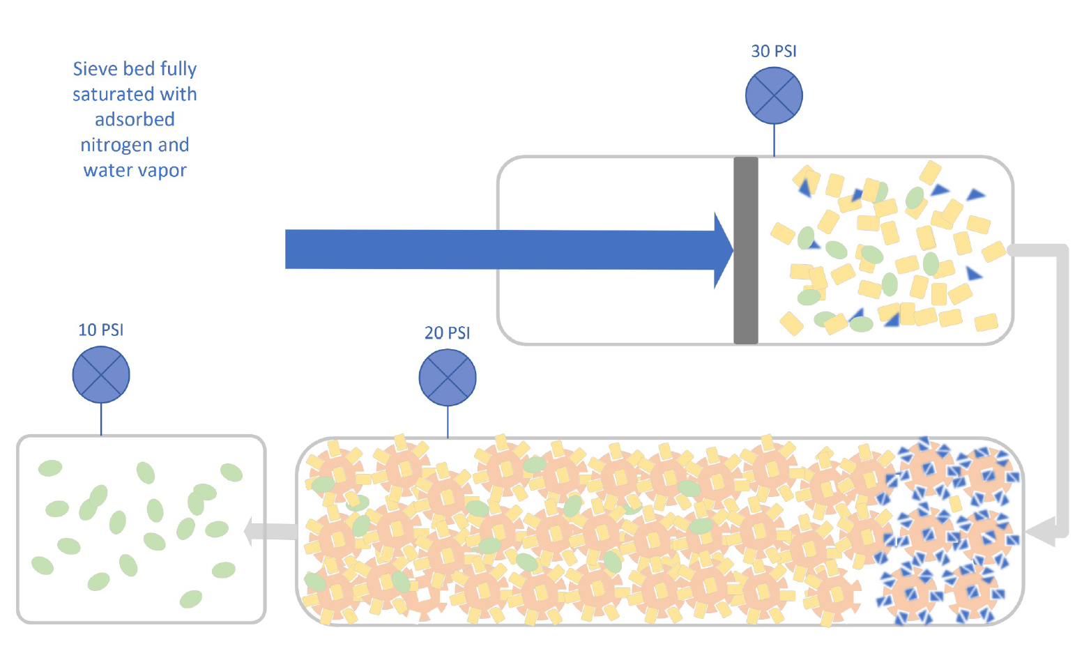
As the air flows through the pressurized molecular sieve, it reaches a point of complete saturation and can hold no more nitrogen.
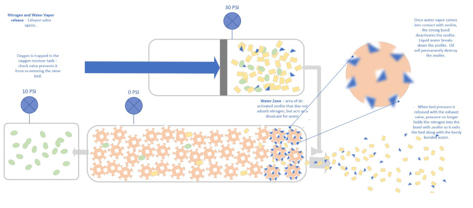
When the air inlet end of the cylinder is opened to atmosphere, the drop in pressure within the cylinder allows the nitrogen to release from the molecular sieve and rush out, carrying some of the water vapor with it (purge cycle). A layer of de-activated sieve remains at the air inlet. This “water zone” will continue to serve as a desiccant that adsorbs water under pressure, but no longer will adsorb nitrogen.
Using two sieve beds together enables the compressor to continue filling one sieve bed and collect oxygen while the other sieve bed is discharging the nitrogen and water vapor. A total of seven valves are used to control the flow of gas:
- 2 feed valves - air inlet valves
- 2 waste valves – nitrogen and water vapor outlet valves
- 2 check valves – prevent oxygen from flowing from the O2 storage back to the sieve
- 1 Equalization “EQ” valve – allows flow of gas from the pressurized sieved bed to the purged sieve bed during a brief interval between cycles.
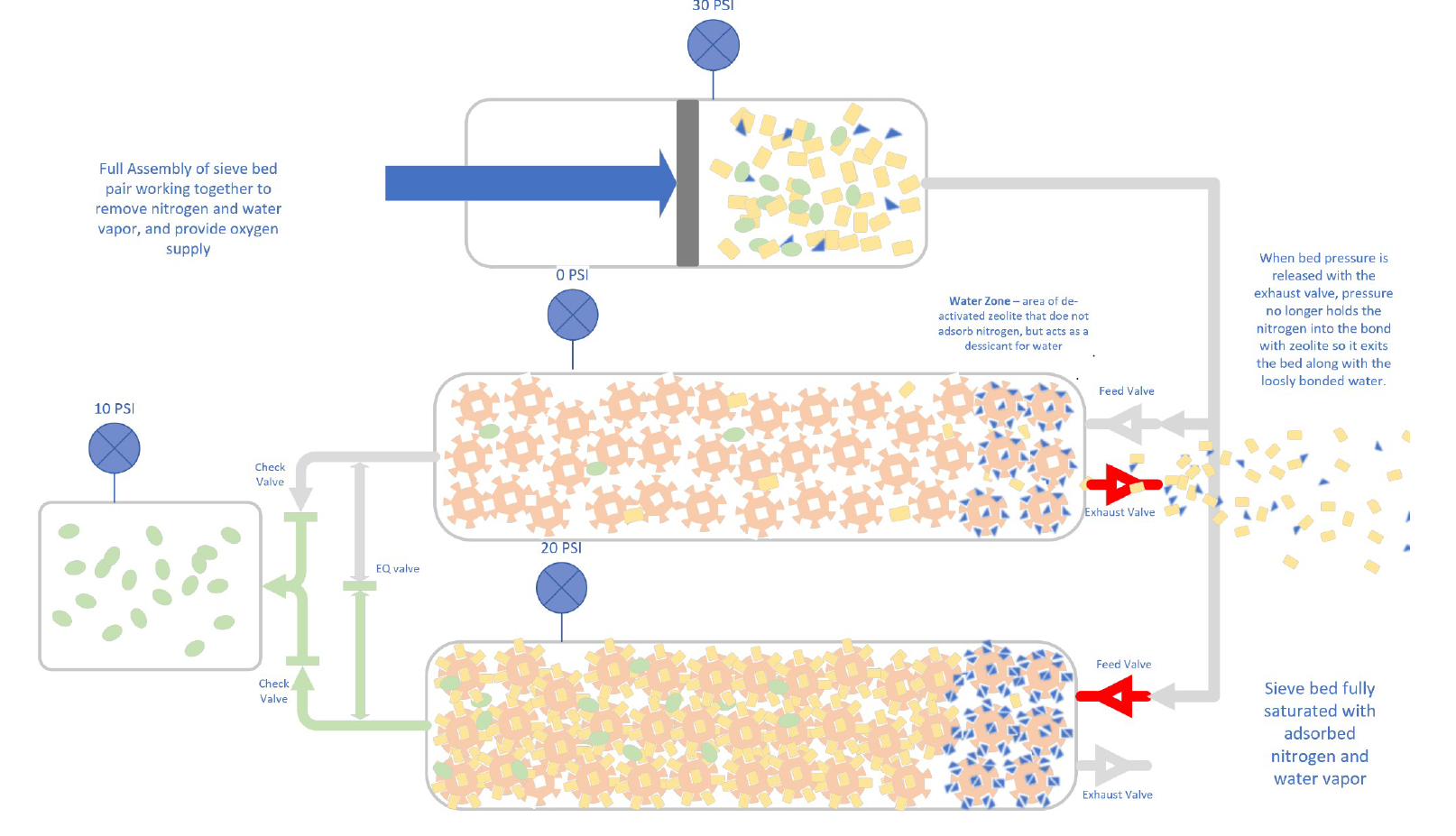
The EQ valve is activated for a short time after the exhaust/waste valve closes and before the feed valve opens. The purpose is to build some pressure with oxygen before the feed valve opens so that the nitrogen will be adsorbed instead of passing completely through the sieve bed. Without pressure, the nitrogen is not adsorbed.
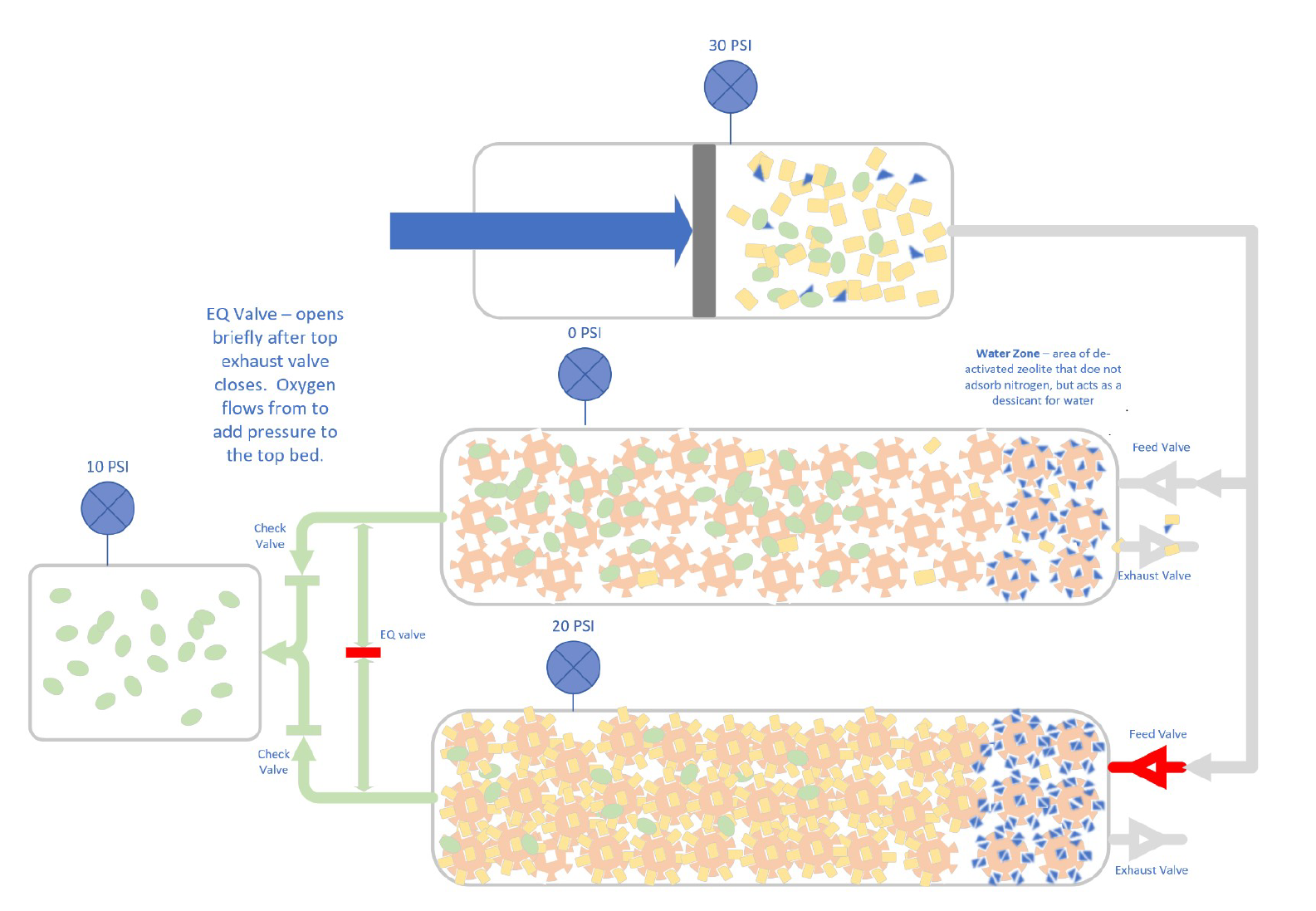
When the EQ valve closes again, the exhaust valve of the saturated sieve bed opens, and the feed valve of the purged sieve bed opens.
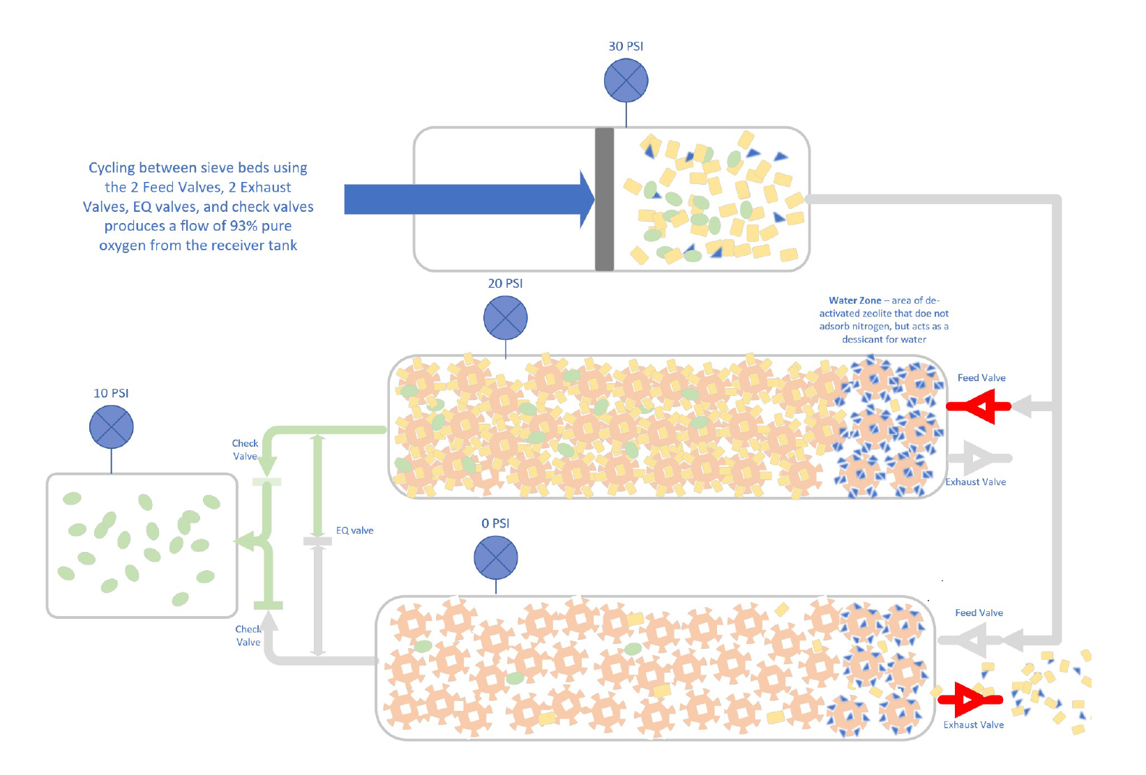
Oxygen collected in the receiver tank can be released for use only as fast as it is collected. If the flow of oxygen from the receiver tank exceeds the capacity of the sieve bed, nitrogen will flow into the oxygen receiver tank and reduce the oxygen purity, and excess water vapor will compromise the molecular sieve.