OC-P1 - Major Rebuild Kit
Related Products


Description / OC-P1 - Major Rebuild Kit
Rebuild Kit Instructions:
DISASSEMBLY
STEP 1. Clean external surfaces of compressor.
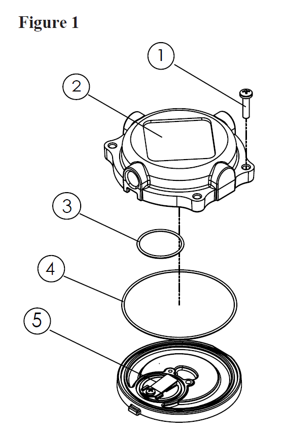
STEP 2. Loosen and remove the 4 head screws (1) and compressor head (2) (Figure 1).
STEP 3. Carefully seperate valve plate (5) from head.
STEP 4. Discard valve plate assembly and cylinder o-ring. Remove and discard orange colored head O-ring(4) and black colored exhaust cavity O-ring (3).
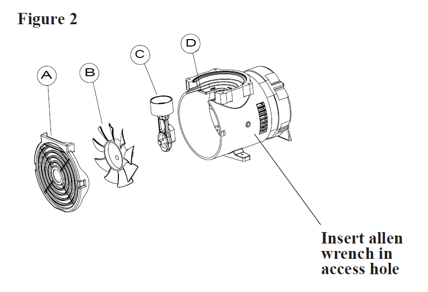
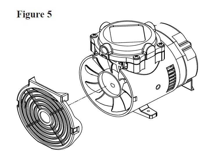
STEP 5. Remove front cover(A) (Figure 2). Remove fan (B) from eccentric bear-ing assembly (C).
STEP 6. Rotate eccentric bearing as-sembly to align set screw with eccentric set screw access hole. Loosen set screw with 1/8 allen wrench. Slide con-necting rod assembly off shaft. Remove from housing and discard.
REASSEMBLE ROD, VALVE PLATE ASSEMBLY AND HEAD
STEP 7. Insert new rod assembly through opening in the housing. Align eccentric set screw with the flat of the shaft. Push assembly onto shaft until eccentric contacts housing bearing.
STEP 8. Torque eccentric set screw to 55 inch pounds.
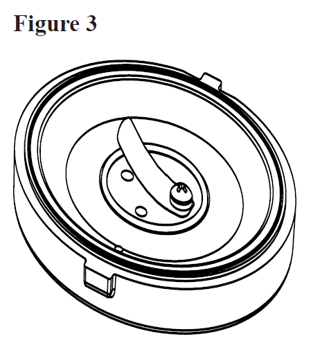
STEP 9. Confirm the new pre-installed cylinder O-ring is fully seated into groove on the bottom of the valve plate (Figure 3).
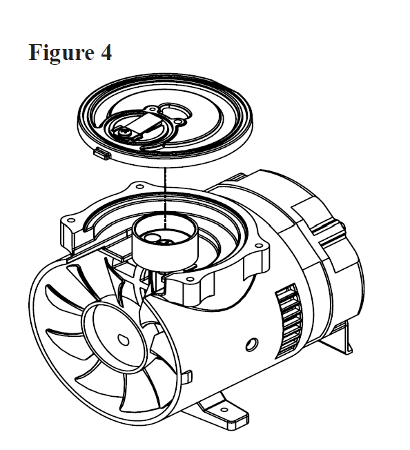
STEP 10. Confirm that cylinder is fully seated and centered on compressor housing shelf (figure 4)
STEP 11. With exhaust valve facing the front, place the valve plate assembly on the compressor hous-ing so the lip of the cylinder fits into O-ring groove on valve plate assembly, ensure cylinder O-ring remains properly seated. (Figure 4)
STEP 12. Carefully install head O-ring and exhaust cavity O-ring, seated firmly into grooves.
STEP 13. Place head on top of valve plate aligning the tabs on the valve plate with the slots on the head and exhaust cavity towards the front.
STEP 14. Insert and tighten 4 head screws to 40 inch pounds in a criss crossed pattern.
REASSEMBLE FAN AND FRONT COVER
STEP 15. Assemble fan onto nib of the connecting rod assembly ensuring that the flat on the nib aligns with the flat of the fan hub. Press firmly until fan touches connecting rod bearing
STEP 16. Assemble front cover to housing by snapping slots on side of front cover onto tabs on side of the housing.
Downloads:
More Information
| Listing Description | Major service kit for LP12 SS |
|---|---|
| Unit Features | Major service kit for LP12 SS |
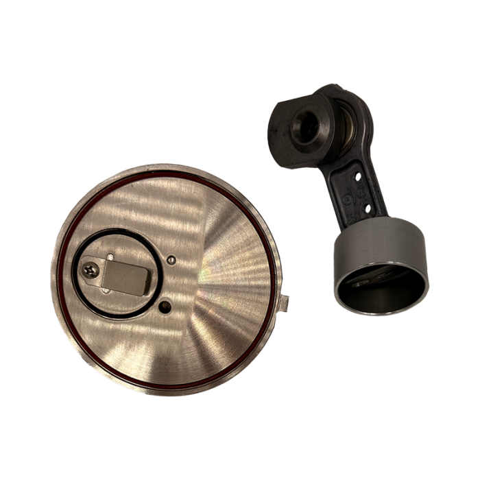
| Features | Major service kit for LP12 SS Includes the rod & ecc assy with SS cup retainer along with the SS valve plate and all orings and valves. |
| Manufacturer | Oxidation Technologies |
| Warranty | 1 Year |