Ozone Applications

Backflow Prevention
Ozone Water System Back Flow Protection:
An important function of every ozone water system is back flow protection of water into the ozone generator. Ozone is generated as a gas and dissolved into water with mechanical mixing equipment. Ozone gas is generated electrically using either corona discharge (most common) or UV lights. In either scenario, it is paramount that water does not flow backward into the ozone generator causing damage.
Ozone gas is dissolved into water using a wide variety of methods, more on those methods here, therefore there are a variety of options to prevent water ingress into an ozone generator, with various advantages and disadvantages. The device used should be determined based on your specific application, the potential risks, and potential maintenance requirements.
In normal operation, ozone gas flows to the water. Therefore, only when the ozone system is OFF, or in upset conditions does water have the potential to flow backward toward the ozone gas outlet side of the ozone generator. A few potential upset conditions and how they react with back-flow devices are listed below:
- High water pressures can occur with a venturi injector or direct injection with a static mixer. When the ozone system is OFF, or when restrictions occur on the downstream side of the water system. High water pressures will force many check-valves closed with pressure. However, high water pressures may leak past some check valves with a ball and seat that do not seal perfectly or leak past automated valves designed to close and prevent water ingress.
- Low water pressures commonly occur with bubble diffuser systems but may occur with other systems when the system is OFF and idle. Low water pressures cause failures with low crack pressure check valves that do not have a positive seal, water can slowly leak past the check valve toward the ozone generator.
- Debris created from poor quality ozone gas feed-gas, formation of nitric acid, dirty water from the water system may cause obstructions to keep an automated electric valve or check valve open.
- Electrical failures that cause certain process equipment to shut down while other process equipment remains operating may force water toward the ozone generator before automated valves or proper shut-down equipment can operate properly.
Below is information on various devices used to prevent the ingress of process water into an ozone generator output. In most applications, a single device is not sufficient, but a combination of devices is used to prevent each of the upset conditions listed above along with unexpected upset conditions. Consider your specific application, maintenance requirements/abilities, and overall risk when choosing the proper equipment for your ozone system.
As always, should you have questions, feel free to contact our Ozone Application Experts.
Check Valves:
Check valves are a simple, economical, and relatively effective method at preventing the back flow of water into an ozone generator. A check valve is a simple device that allows gas to flow in only one direction, they may sometimes be referred to as a one-way valve.
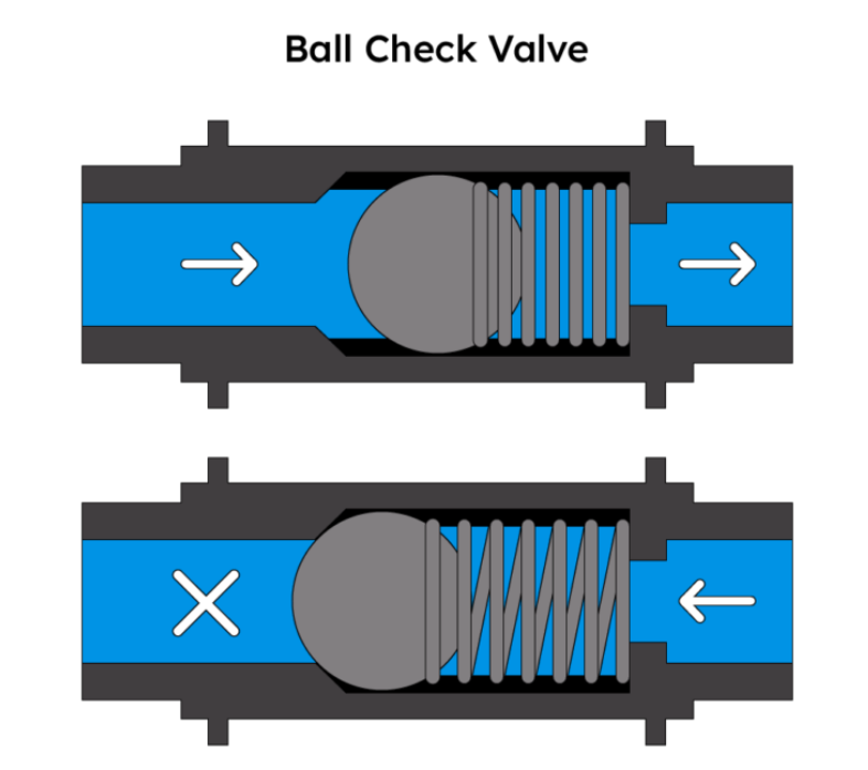
A check valve uses mechanical means to prevent the back-flow of water. This may include a spring, ball, seal, flapper, and/or other components. In all scenerio there are mechanical, moving components to allow flow of gas in only one direction. Due to the moving parts, and mechanical nature all check valves will eventually fail. Therefore, the check valve must be replaced on a maintenance schedule, prior to any potential failure.
Installation Tips:
-
Crack pressures range between nearly 0 PSI to 10 PSI. The crack pressure indicates the gas pressure (or vacuum) necessary to open the check valve and allow flow of gas in the intended flow direction. Higher crack pressures provide a better seal but may wear out the seal and spring faster. Lower crack pressures provide a less positive seal but may be required based on the ozone gas pressure (or vacuum) available in your specific system.
Higher crack pressures may also restrict gas flow if ozone gas pressure is limited.
-
Multiple Check Valves inline in series is a great method of providing additional reliability and safety without a high cost. We suggest using various check valve designs and crack pressures inline to protect your system in a wide variety of upset condtions.
-
Cv factor, or Valve Flow Coefficient generally refers to the gas flow restriction caused by the check valve. A higher Cv factor indicates a lower restriction, and higher flow ability of the check valve. Cv factor is not usually a major factor for ozone gas flows and check valves, but when combined with a high crack pressure and a limited output pressure ozone generator, the effect Cv factor should be considered.
-
Service/Replacement is required with check valves long-term, therefore ensure the check valve is installed in a location and manner that make future service possible.
-
Can be used with a venturi injector or bubble diffuser, however higher pressure applications such as direct injection into pressurized water lines prior to static mixers will not be suitable.
Advantages of check valves:
-
Low cost
-
Simple to install
Disadvantages of check valves:
-
Moving parts, the mechanical nature of construction will cause failure
-
Restricts gas pressure/flow
J-Tube:
Also known as a Balance Barometer, or Atmospheric Water Trap.
This is a very simple design to ensure gas can flow from the ozone generator to the venturi while preventing water backing into the ozone generator with excellent reliability. See diagram below for an example of this device installed.
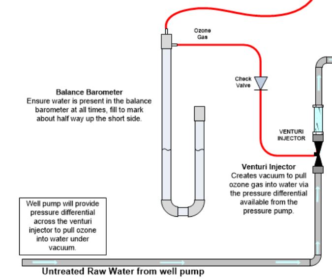
The use of a J-Tube is better suited for a vacuum system where the venturi is drawing a vacuum from the ozone generator. The J-Tube will balance the vacuum from the venturi with the vacuum required to draw ozone from the ozone generator.
-
When the vacuum necessary to draw ozone gas from the ozone generator is too high the water level on the closed section rises and water may be sucked into the venturi.
-
When water flows backward from the venturi toward the ozone generator the open end of the J-Tube will pour water safely on the ground (hopefully near a drain)
Installation Tips:
-
Vacuum operation is ideal. Ideally the J-Tube is used with a vacuum driven ozone generator, operating the J-Tube under pressure makes balancing the pressure vs vacuum very challenging.
-
Check Valves should still be installed to slow water flow from the venturi, the J-Tube is used as a final safety back-up
-
Water Levels in the J-Tube need to be checked and potentially filled frequently, when the J-Tube runs out of water it will not allow any vacuum from the ozone generator as it cannot balance the vacuum to water height. This is why the J-Tube is also referred to as a Balance Barometer.
-
Only viable for installation with a venturi injector
Advantages of the J-Tube:
-
Lowest cost
-
Extremely reliable
Disadvantages of the J-Tube:
-
High maintenance, water level is important
-
Only works well under a vacuum
-
High flow, high vacuum situations will not function well, only suitable for small systems
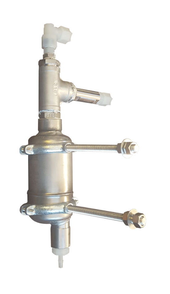
Water Trap:
A water trap is a device that can capture water that does flow backward toward an ozone generator, trap this water, and safely drain this water. A water trap can be operated under pressure, or vacuum. We use an 11AV or a 1-AVCW air vent in an “upside down” configuration as a water trap. Each works well. A check valve is still required to at least slow the flow of water in an undesirable direction and allow the drain function to keep up with water flow.
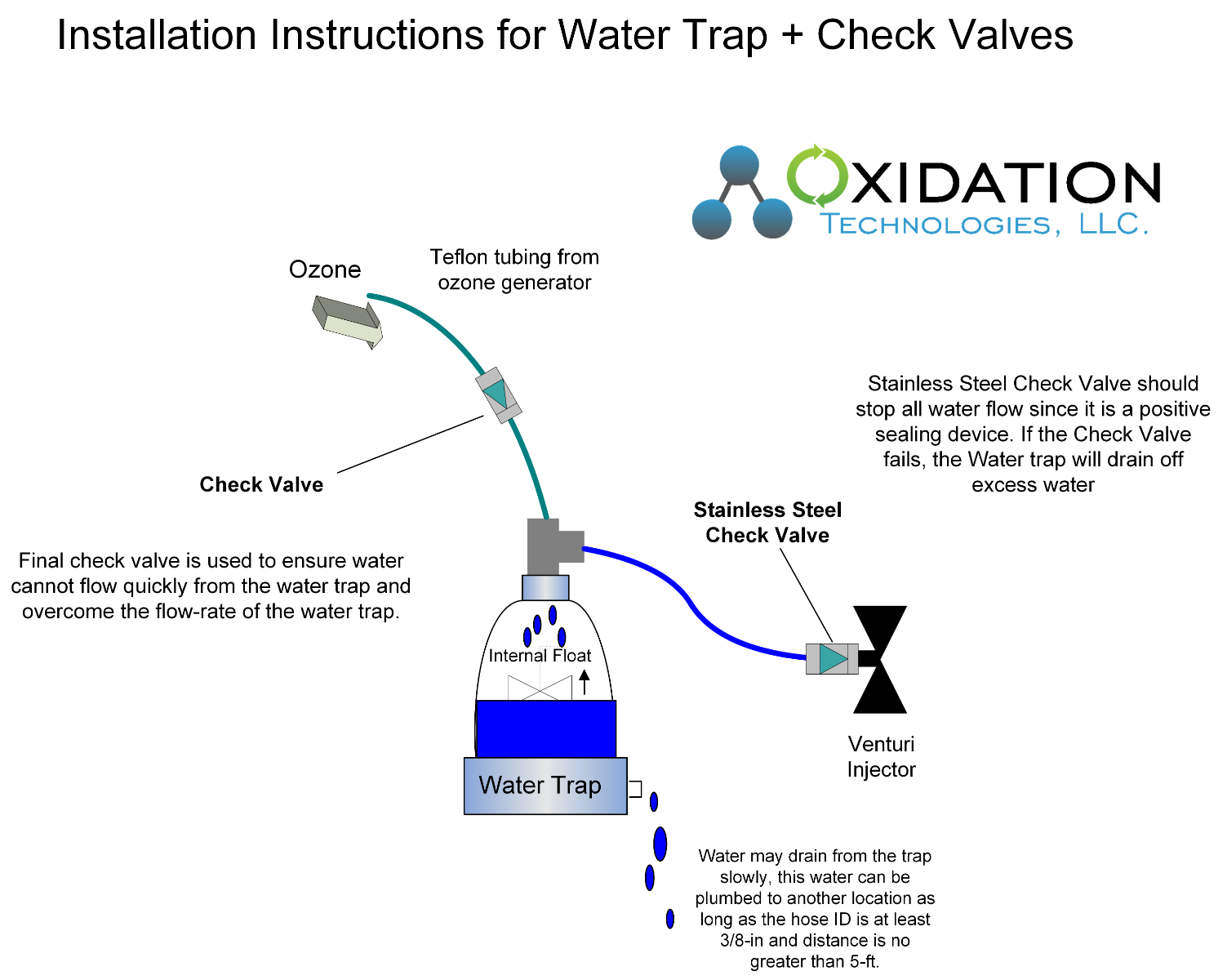
All captured water can be drained safely from the system while not allowing ozone gas to escape from the system.
Installation Tips:
-
Check valves, or similar should still be used with the Water Trap to prevent water flow and keep water draining to a minimum. Check valves will also slow the flow of water to ensure the flow of water from the ozone injection device does not overwhelm the drain capacity of the water trap
-
Vacuum systems can potentially lift the float on the water trap. Therefore, when used with a venturi that draws a large vacuum from the ozone generator this may cause air to enter the water trap. Keep vacuum on the water trap to a minimum.
-
Water will drain from the water trap. Ensure this water can drain to a safe location, and ensure the tubing used for the drain is of sufficient size for the drain distance and potential volume of draining water.
-
The 11AV is stainless steel and very suitable for high ozone concentration applications
-
The 1-AVCW is a clear material that allows a visual indication of the status and operation, however, ozone concentrations should be kept to 5% or lower for reliable operation
-
When used properly, the water trap can be used with a venturi injector, bubble diffuser, or Static mixers. The water trap is a great solution for high-pressure ozone gas applications.
Advantages of a Water Trap:
-
Reliable operation should be considered for all high-risk applications
-
Operates well with high ozone gas pressure applications
-
No electronic parts ensure operation in all conditions
Disadvantages of a Water Trap:
-
Higher cost than other options
-
Moving parts, this system will require some maintenance long-term
-
Does not work well with high vacuum applications
Automated Valve:
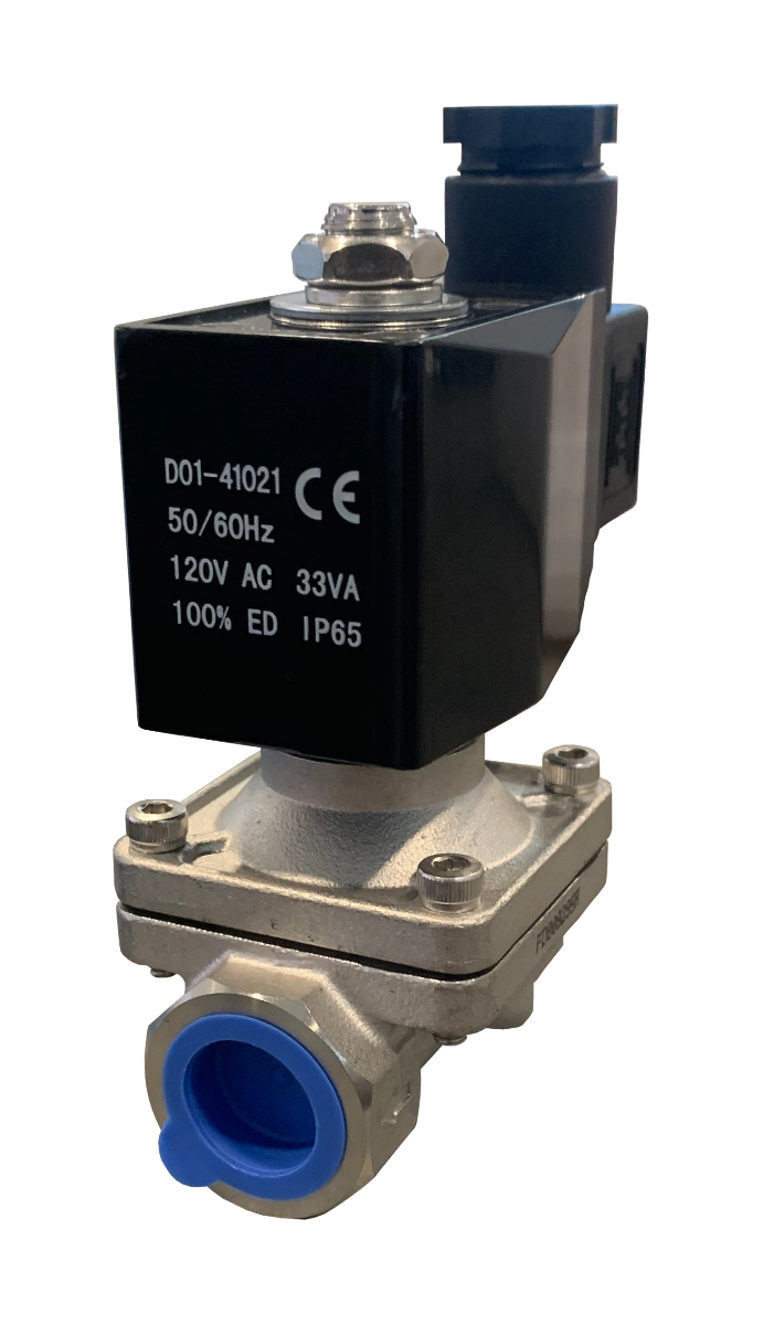
An ozone-resistant Solenoid Valve or Electronic Ball Valve can be used.
An automated valve can be used with your ozone systems control system to Open and Close only when safe. The automated valve can also be used separately with a water sensor or vacuum/pressure sensor and set to close when either low pressure or water is detected.
|
|
|
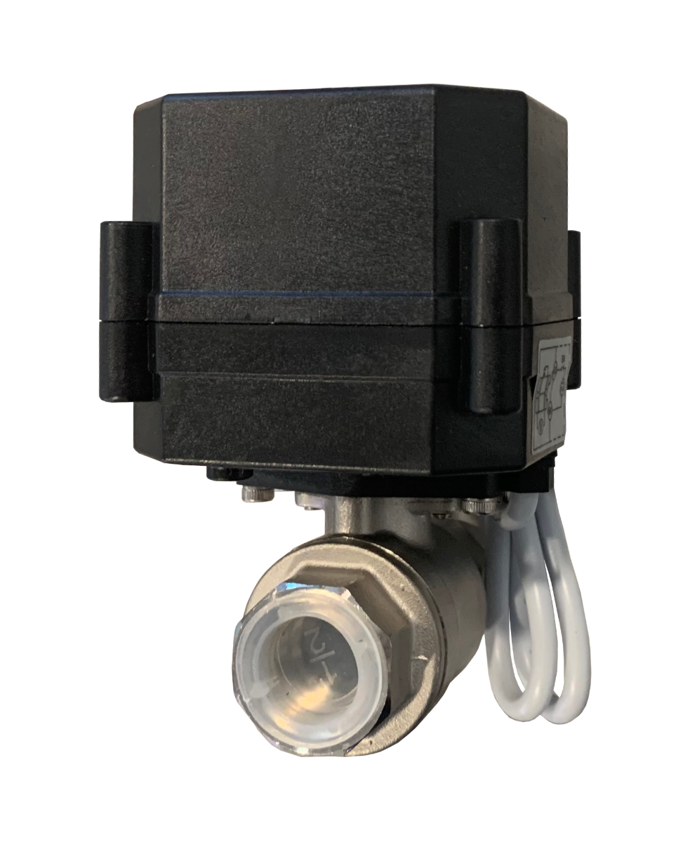
We prefer the Electronic Ball Valve due to the positive seal and the lack of diaphragms to fail. The Normally Closed Electronic Ball Valve we use contains a capacitor to close the valve electrically in the event of a power loss.
This is an excellent method of keeping an ozone generator safe from water ingress. However, due to the mechanical moving parts and electrical requirements there are a great deal of potential failure points to this system. Maintenance is critical!
Installation Tips:
-
Water sensors can be used to detect the presence of water in the ozone line. When water is detected, the valve is closed. Water sensors are simple and reliable. However, ozone resistance is important and a variety of electrical failures can occur causing potential failure.
-
Vacuuum/Pressure Sensors can be used on the ozone line to indicate a loss of vacuum from the venturi, or a loss of pressure from the ozone generator. Either scenario would be an upset condition that could allow water to flow toward the ozone generator.
-
Ozone resistance should be a consideration with high ozone concentrations. A diaphragm-based solenoid valve may not be suitable with ozone concentrations above 5% by weight. In higher ozone applications consider a motorized ball valve.
-
Reaction time may insufficient in some upset conditions. With high flow coefficients and high water pressures it is possible to push water into the ozone generator before the valve can fully close and protect the ozone generator. Consider adding a check valve to the system and placing the valve close to the water source rather than the ozone generator.
-
Power outages may cause failures if a water sensor or pressure sensor is used and relied upon to close the valve.
-
Back-up systems should be considered as the valve is mechanical and prone to long-term failure. Also electronic failures in an upset condition may allow water to back-up toward the ozone generator.
-
When used properly, an automated valve can be used with a venturi injector, bubble diffuser, or Static mixers. This is a great solution for high-pressure ozone gas applications.
Advantages of an Electronic Automated Valve:
-
Positive closed seal
-
Works well for high-pressure applications
-
Handles high flows of ozone gas
Disadvantages of an Electronic Automated Valve:
-
Higher cost than other options
-
Moving parts, this system will require some maintenance long-term
Summary:
Within ozone water systems water ingress into the ozone generator is one of the highest failure modes of the system.
There is no single one-size-fits-all solution that suits every application. And in most applications, a combination of the suggestions above should be considered to be completely safe.
We supply a system that we believe to be a solid solution in a wide variety of applications that offers superb reliability. The BFP-SS combines the use of a water trap with two different types of check valves.
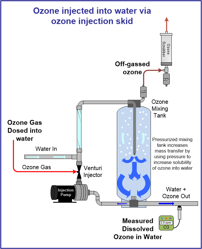
The image below shows the BFP-SS Back Flow Preventer used with a simple ozone generation system using a vacuum-driven ozone generator and air dryer. The Venturi Injector is used to produce suction/vacuum to pull ozone gas from the air dryer, through the ozone generator and into the water through the Venturi Injector.
When water flow through the venturi stops, suction on the ozone line also ceases. This will cause water pressures to exist on the suction port of the venturi injector. In this scenario, water may flow from the venturi, toward the ozone generator.
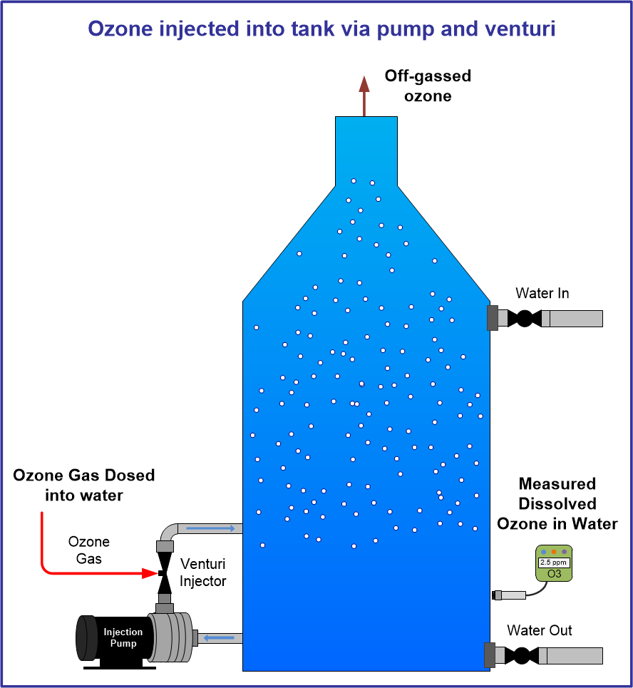
The image below shows a more complete system using an ozone generator producing ozone from oxygen under pressure. This oxygen/ozone gas is pushed, under pressure, toward the venturi injector. However, in some cases ozone/oxygen gas pressure can overcome water pressures and push gas into the water, under pressure to be mixed later with a static mixer.
In the scenario shown below, when the ozone injection pump turns OFF, the head pressure of the water tank will push water out the ozone injection point and toward the ozone generator.
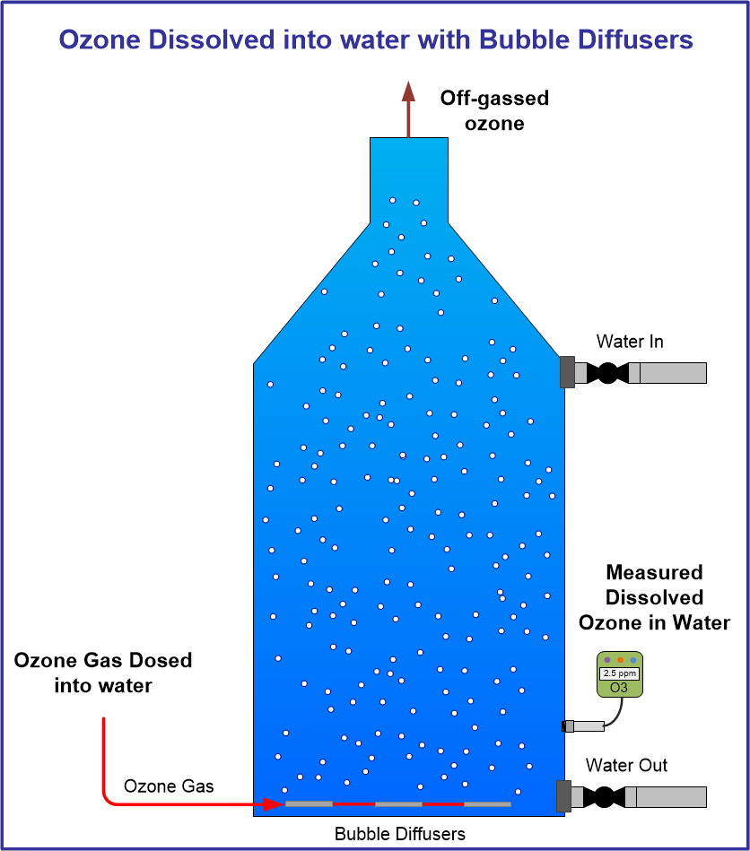
The images below shows a simple system where ozone gas is produced from oxygen under pressure and pushed to a fine pore bubble differ to bubble ozone gas into water and dissolving into water.
In this system, when the oxygen concentrator is turned OFF, or fails, water height from the tank will push water slowly, toward the ozone generator. This type of system is one of the most difficult to protect against water back-flow as the water pressure is low causing the check valve to not seat properly and slowly leaking water toward and into, the ozone generator. These systems may use oxygen concentrators and ozone generators with limited pressure capability due to the low pressures needed to push ozone/oxygen through the diffuser. Due to this, a high crack pressure check valve may not be suitable.
If you are using a bubble diffuser to bubble ozone into a water tank, take extra precaution to prevent water back-flow into the ozone generator.
Two additional considerations when using ozone bubble diffusers in tanks.
- We have seen some installs use an ozone gas line that rises above the tank, then drops to the tank in the hopes that this tubing height breaks the pressure from the tank. However, in upset conditions when the tank pressure rises slightly due to venting issues, or other upset conditions, this tall tubing loop becomes a very effective siphon delivering water very efficiently directly to the ozone generator.
- Mounting the ozone generator above the water height is a great consideration. In those cases ensure the tank is vented well with no potential vent failures. A very slight water pressure in the tank due to poor venting, while the tank is filling, may cause water to push toward the ozone generator.
Additional Information on Ozone System Design Below: